
Circuit Analysis of 3 Phase System electrical and electronics technology degree
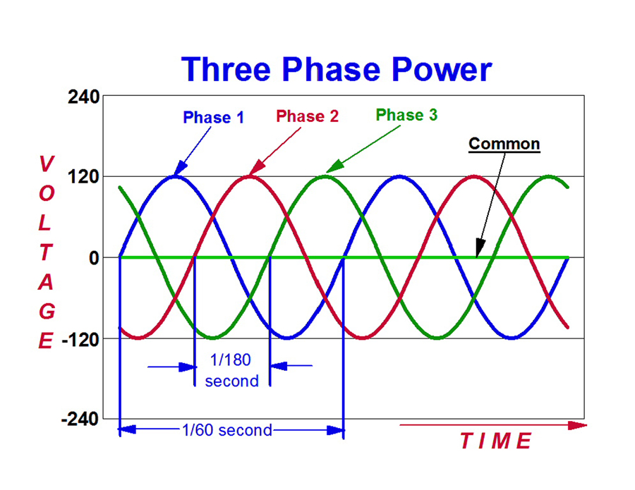
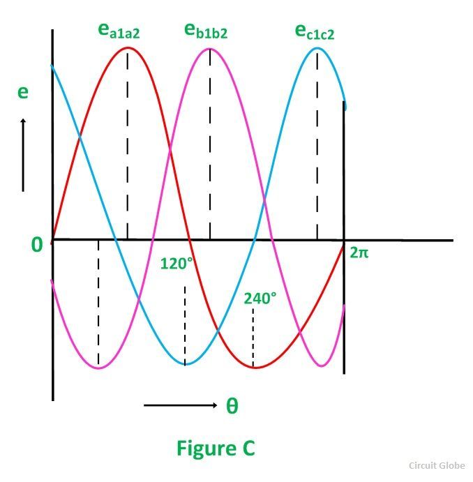
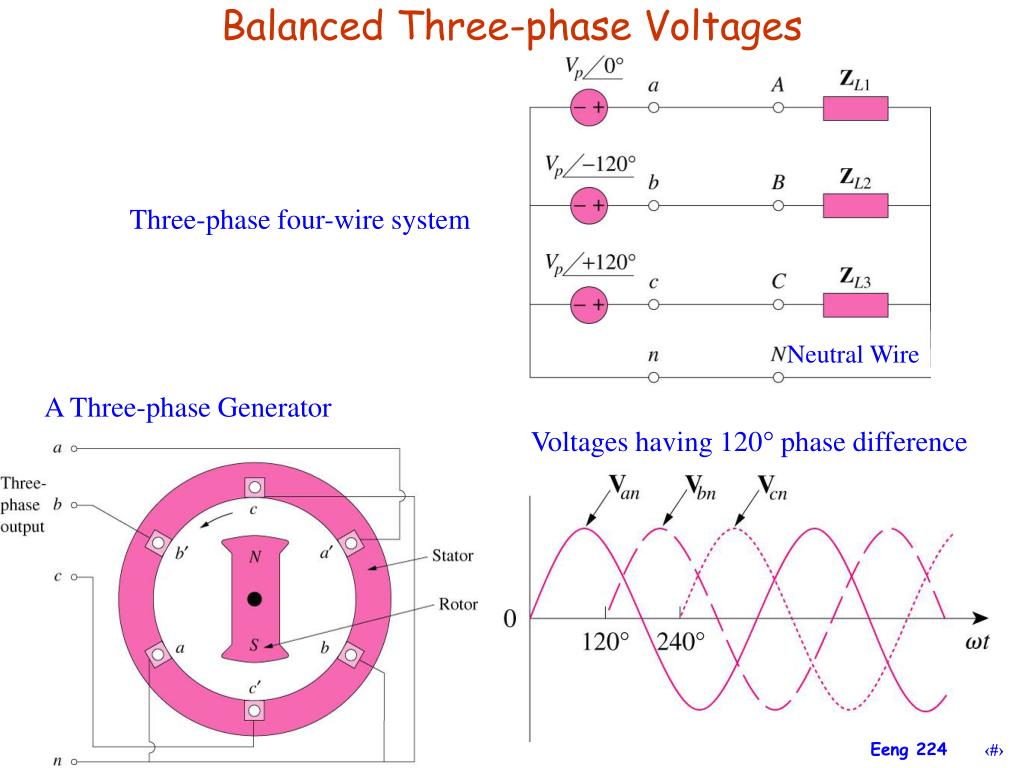
Three phase electricity consists of three AC voltages of identical frequency and similar amplitude. Each AC voltage 'phase' is separated by 120° from the other (Figure 1). Figure 1 - Three-phase voltage waveform This can be represented diagrammatically by both waveforms and a vector diagram (Figure 2). Figure 2 - Three-phase voltage vectors
Why do we have 3 Phase Industrial Heaters? Thermal Corporation
3-phase AC circuits. Circuits or systems in which the ac sources operate at the same frequency but different phases are known as polyphase. Figure 1 shows a three-phase four-wire system. As distinct from a single-phase system, a three-phase system is produced by a generator (alternator), whose cross-sectional view is shown in Figure 2 (a).
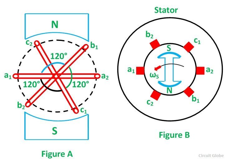
Generation of 3 Phase Power in 3 Phase Circuits Circuit Globe
A single line voltage referenced to a neutral Electrical power is generated, transmitted, and largely consumed (by industrial customers) as three-phase power Three individual line voltages and (possibly) a neutral Line voltages all differ in phase by 4 Δ- and Y-Connected Networks Two possible three-phase configurations
Three Phase Delta Connection Three Phase Power,Voltage,Current Electrical Academia
In electrical engineering, three-phase electric power systems have at least three conductors carrying alternating voltages that are offset in time by one-third of the period. A three-phase system may be arranged in delta (∆) or star (Y) (also denoted as wye in some areas, as symbolically it is similar to the letter 'Y').
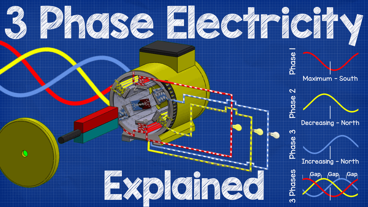
Three Phase Electricity Explained The Engineering Mindset
Three-phase "Y" connection has three voltage sources connected to a common point. If we draw a circuit showing each voltage source to be a coil of wire (alternator or transformer winding) and do some slight rearranging, the "Y" configuration becomes more obvious in Figure below. Three-phase, four-wire "Y" connection uses a "common" fourth wire.

Three Phase Electrical Wiring Installation in Home NEC & IEC Tutorial
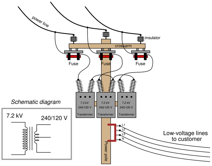
Three-phase power is a three-wire ac power circuit with each phase ac signal 120 electrical degrees apart. Residential homes are usually served by a single-phase power supply, while commercial and industrial facilities usually use a three-phase supply.
Generation of 3 Phase Power in 3 Phase Circuits Circuit Globe
A three-phase circuit is like having three separate AC single-phase circuits with identical voltage that reach their peak values at a different time. At 60 hz, the second phase reaches its positive peak at 1/180 (0.00556) seconds after the time the first phase reaches a positive peak, and the third phase reaches its positive peak 1/180 (0.00556.
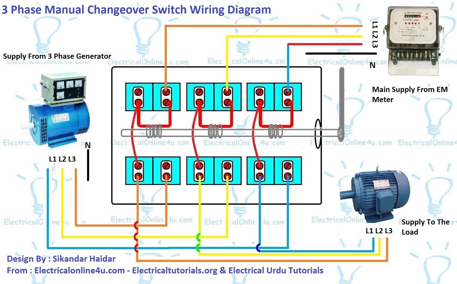
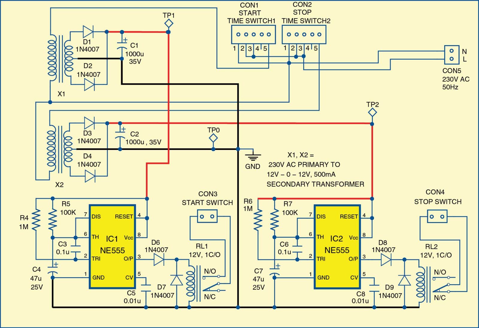
3 Phase Automatic Changeover Switch Circuit Diagram Pdf
When there are three lines carrying three-phase electricity, the voltage between every two lines is called line-to-line or simply line voltage. In the presence of a fourth line, the voltage between each line and the common point (or the null line) is called phase voltage. This is irrespective of how the connection is at the source.
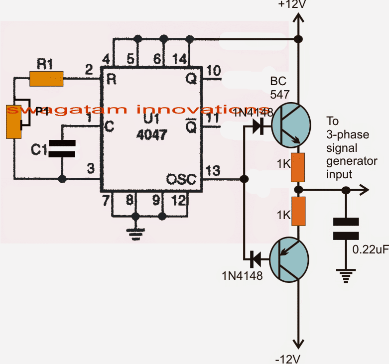
Simple 3 Phase Inverter Circuit Homemade Circuit Projects
Basically, we just multiply amp by volts. The '1,000' factor is there to convert from W to kW; we want the resulting power to be in kilowatts. 1 kW = 1,000W. Compared to this, the 3-phase power formula is a bit more complex. Here's the 3-phase power equation: P (kW) = (I (Amps) × V (Volts) × PF × 1.732) ÷ 1,000
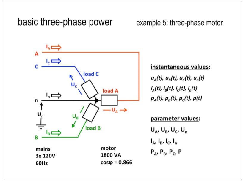
Electrical Power Explained Part 3 Balanced threephase AC power Fluke
three phase electricity explained How does three phase electricity work? In this article we'll be explaining how three phase electricity works, we'll start from the basics of a single phase alternating current generator and then add in a second and third phase to understand how three phase electricity works.
PPT Chapter 12 Three Phase Circuits PowerPoint Presentation, free download ID3226793
Visit http://ilectureonline.com for more math and science lectures!In this video I will explain what is 3 phase circuit. Using a typical household circuit th.
Three Phase AC Circuits Worksheet Electricity and Electronics
Three phase circuit is the polyphase system where three phases are send together from the generator to the load. Each phase are having a phase difference of 120 o, i.e 120 o angle electrically. So from the total of 360 o, three phases are equally divided into 120 o each.
Three Phase Transformer Connections Phasor Diagrams Electrical Academia
Definition: The system which has three phases, i.e., the current will pass through the three wires, and there will be one neutral wire for passing the fault current to the earth is known as the three phase system. In other words, the system which uses three wires for generation, transmission and distribution is known as the three phase system.
Direct Online Starter Animation Diagrams Electrical Online 4u
A three-phase system can be connected to a load such that the number of copper connections required (and thus the transmission losses) is one-half of what they would otherwise be. Consider three single-phase systems each supplying 100 W to a load (Figure 3). The total load is 3 × 100 W = 300 W.
3 Phase Motor Programmable Controller Full Electronics Project
Phase3 (t) = 325 × sin (2π × 50 × t + 2π/3) Figure 1 Top: A three-phase source is three sine voltages with 120-degree phase shifts. Bottom The voltage, when measured between any pairs of phases, is 1.73 times higher than between a phase and the neutral. In that example, the voltage between each phase and the neutral is still ±325V P-P.

Single Phase & Three Phase Power Electric Circuits & System Electrical Engineering 123
In this video we learn how three phase electricity works from the basics. The basics of Three phase electricity explained. We start with a simple single phas.